Errors while running Rust on Virtualbox
Posted by Kristian Golding on August 16, 2020
I got the following error when running “cargo run” on my “Roguelike” follo-along project (https://bfnightly.bracketproductions.com/rustbook)
Err` value: CreationErrors([NoAvailablePixelFormat, NoAvailablePixelFormat])'I found the error was due to 3D acceleration being enabled on my Linux Mint 19-based development environment, running on Virtualbox 6.1.10. That is, make sure you have this in your vboxmanage line in your Vagrantfile:
vb.customize ["modifyvm", :id, "--accelerate3d", "off"] # Disable 3d acceleration until Virtualbox team fixes it
Remembering back as to why I had that line set to “on”, I think I was playing around with getting the Android emulator to work in Virtualbox, which as of 6.1 supports nested virtualization. I came close to getting that working, ultimately I don’t think it’s possible right now.
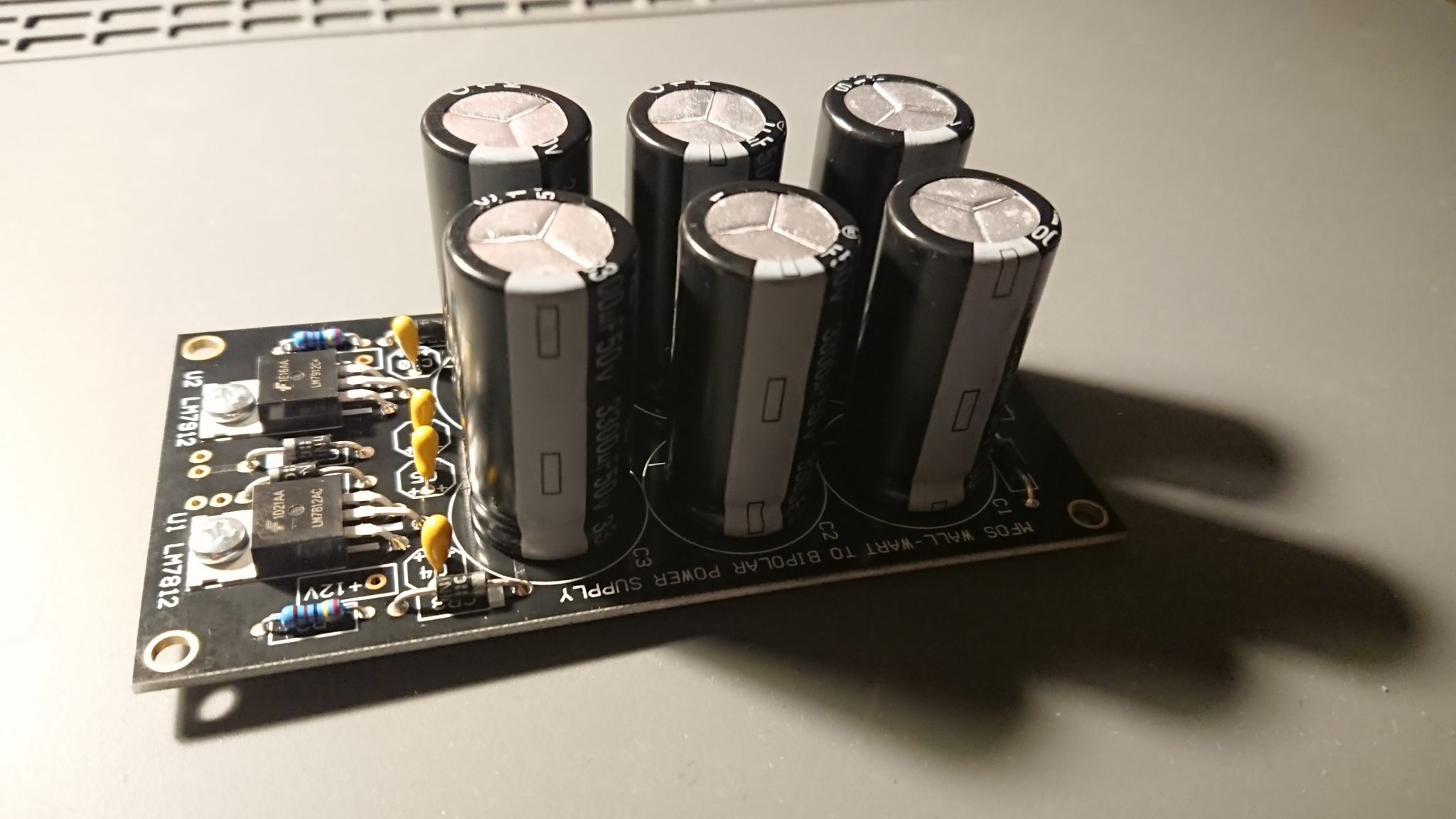
Power supply – MFOS Soundlab mini synth mk II
Posted by Kristian Golding on August 16, 2020
The supply that powers the +/- 12v rails is done! I think I’m about 1% of the way there.
Building the MFOS Sound Lab Mini Synth Mark II
Posted by Kristian Golding on August 11, 2020
This arrived in the mail today from Synthcube
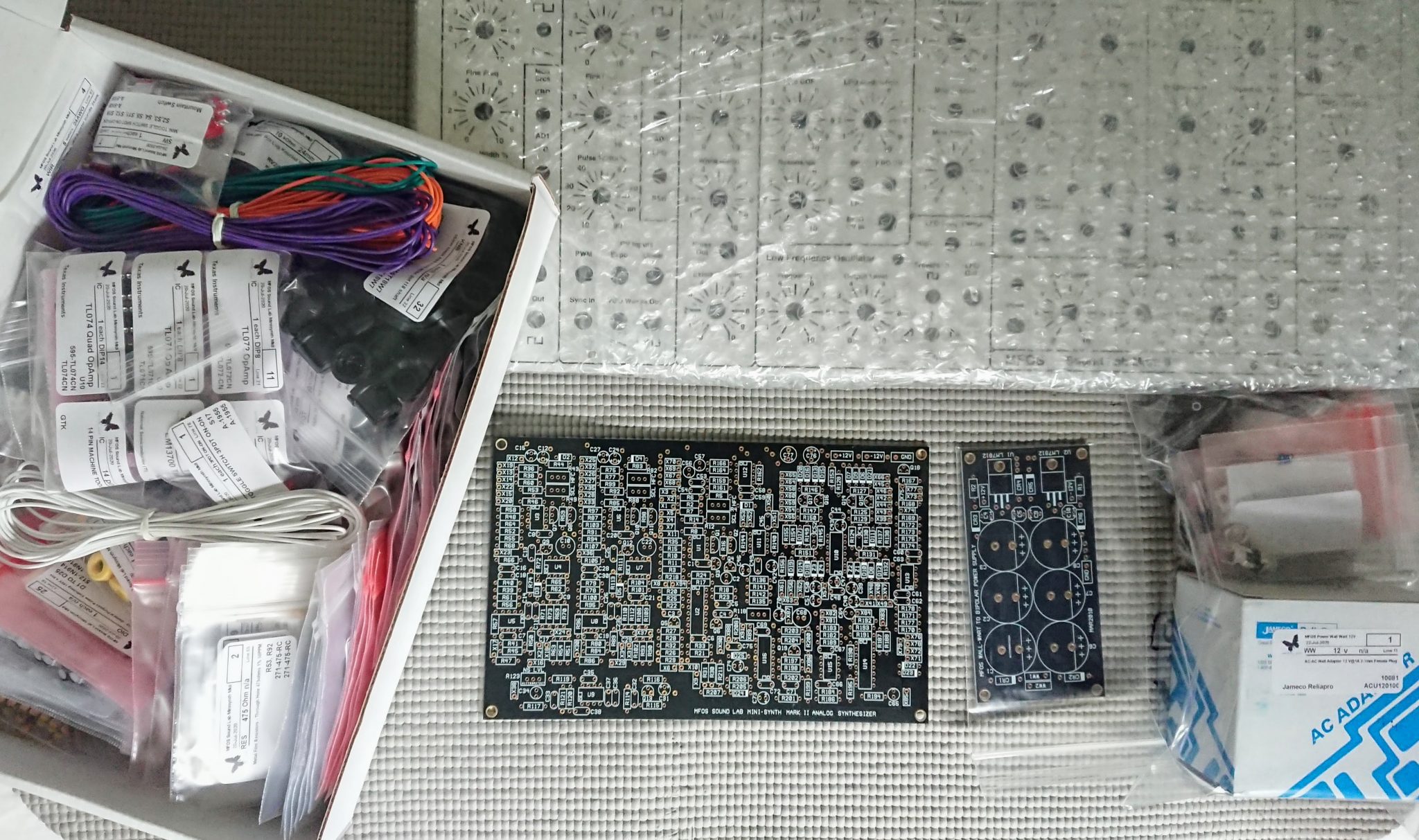
It is the Music From Outer Space (MFOS) Sound Lab Mini Synth Mark II, an analog synth from the great late Ray Wilson. There is quite a lot of involved soldering – though I did do more soldering back in the days when I was constructing the Electronics Australia Playmaster series of pre-/subwoofer/stereo amps, but it actually looks like the wiring to all the pots/plugs may be the killer.
I decided to buy this after going down an analog synth hole in Youtube recently (spurred on by the excellent DIY synth videos by Moritz Klein). I can’t wait to get started, but will have to ease myself into it by building the power supply first. Eventually I’ll have to build a housing for it, and am on the fence between staining plywood or using walnut hobby board. A great project though for these socially isolated times!
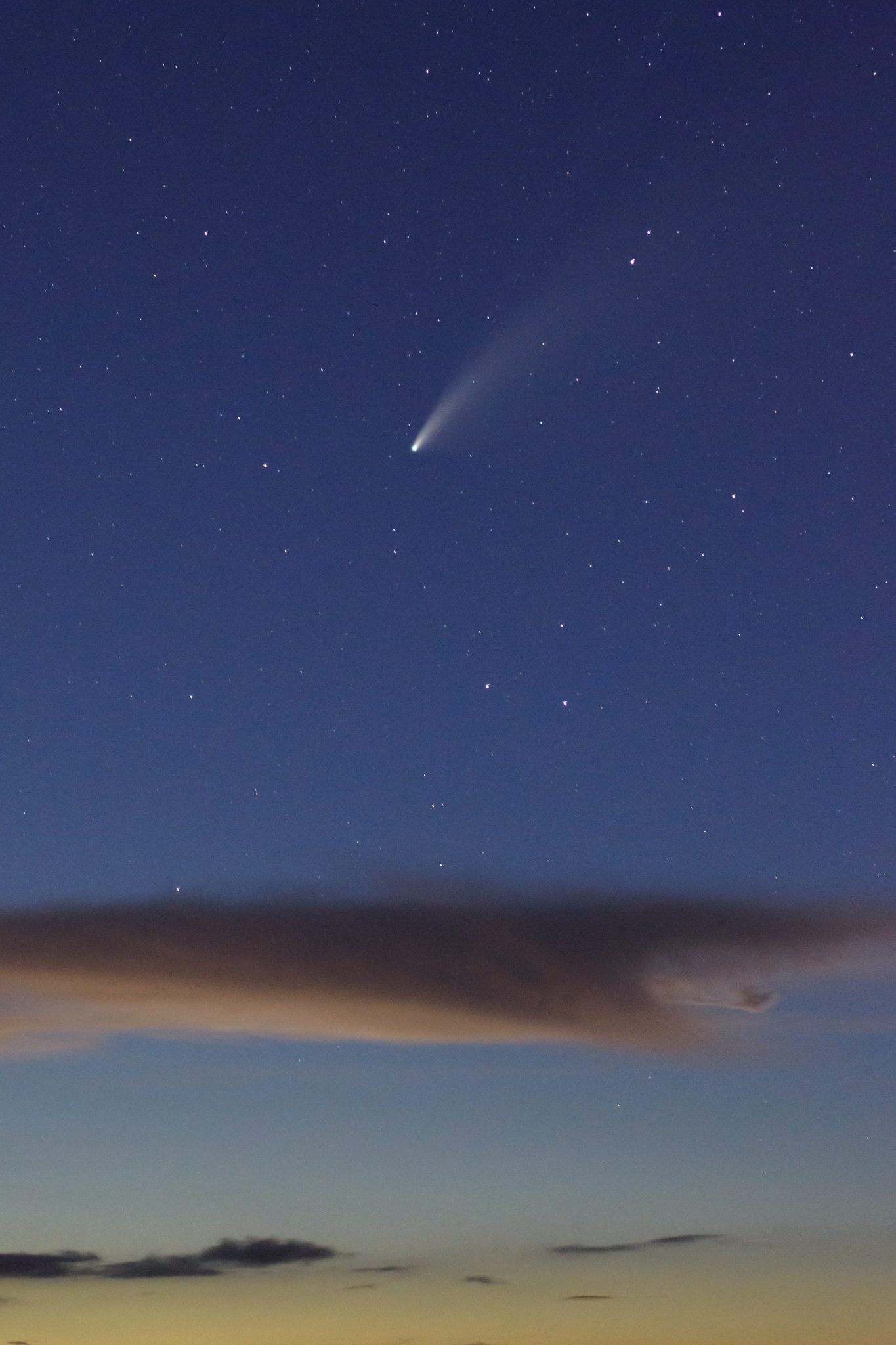
Comet NEOWISE
Posted by Kristian Golding on July 26, 2020
As seen from the Everglades to the west of Miami