Category: android

Android on a Raspberry Pi 4 – Part 1 – Building the images and setting up the sdcard

As I’m fresh-out of Android development boards, I decided to try and repurpose a Raspberry Pi 4 for Android experimentation in preparation for when the next version of this book comes out: http://newandroidbook.com/. I had originally tried this with my Raspberry Pi 3A+, but only found real support for the 3B.

First, you need a version of Android that is customized for the Pi 4 . I used this repo and followed the guide: https://github.com/android-rpi/device_arpi_rpi4

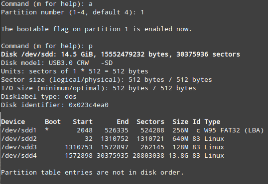
Note: when formatting the SDcard, this is how I did it. First, I listed all disks to find where my SDcard existed, which was /dev/sdd:

sudo fdisk -l

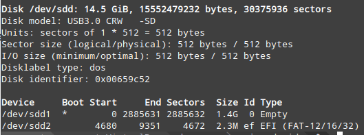
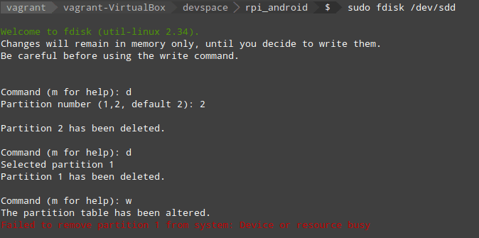
My disk was not empty, so I removed the existing partitions, using fdisk.

Now to create the partitions as specified by the guide, i.e:

# Prepare sd card Partitions of the card should be set-up like followings. p1 256MB for BOOT : Do fdisk : W95 FAT32(LBA) & Bootable, mkfs.vfat
p2 640MB for /system : Do fdisk, new primary partition
p3 128MB for /vendor : Do fdisk, new primary partition
p4 remaining space for /data : Do fdisk, mkfs.ext4

Set volume label for /data partition as userdata : use -L option of mkfs.ext4, e2label command, or -n option of mkfs.vfat

The fdisk command is again used to create the partitions:

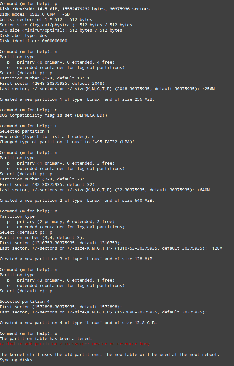
(Forgot to show making the /dev/sdd1 partition a boot partition)

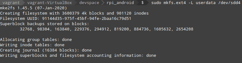
To set up the file systems correctly, I ejected/inserted the SDcard, and ran the following mkfs commands. The first makes /dev/sdd1 a vfat boot partition, and the second makes /dev/sdd4 an ext4 partition with label ‘userdata’.

I then formatted the DOS partition:

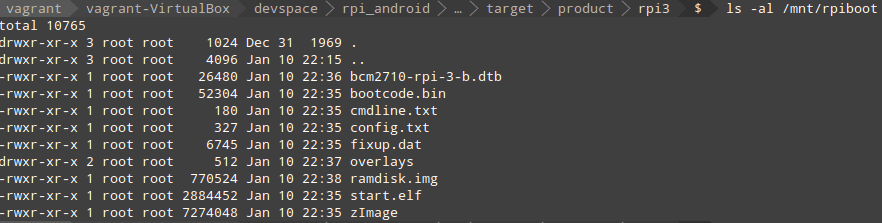
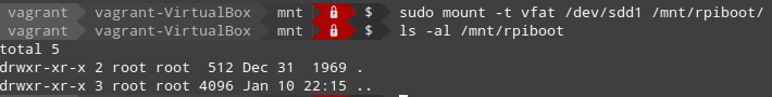
After formatting, I copied the system and vendor images across to their respective locations as shown in the guide. To copy files to the DOS partition, it had to be mounted (I made a directory /mnt/rpiboot):

And then I followed all the commands for copying to the boot partition, the result of which looks like:

A journey with “Embedded programming with Android”: part 1

I purchased the Kindle edition of this book: https://www.amazon.com/Embedded-Programming-Android-Bringing-Scratch-ebook/dp/B013IQGX3A

and since I’m going through the book in 2019, there are a few gaps to bridge.   The first was creating an emulator.  I did this via command line, and step 1 was to get a basic Android SDK downloaded.  I use Vagrant/Virtualbox for my development, so this was used to set up the SDK

put this here

Once that’s done, I need to configure my emulator to use Android API 15.  To get an idea of what I can install, I use the sdkmanager tool to list all the available options:

$ANDROID_HOME/tools/bin/sdkmanager --list

Which gives a bunch of output, but I’m only interested in the android-15 results:

  system-images;android-15;default;armeabi-v7a      | 5    | ARM EABI v7a System Image
  system-images;android-15;default;x86              | 5    | Intel x86 Atom System Image
  system-images;android-15;google_apis;armeabi-v7a  | 6    | Google APIs ARM EABI v7a System Image
  system-images;android-15;google_apis;x86          | 6    | Google APIs Intel x86 Atom System Image

The book says we’ll be developing for arm, and I don’t think I’ll need Google APIs, so Ihoose the armeabi-v7a.  I don’t know how this is all going to fly in Virtualbox either, so I yolo by running the following command and accepting license with “y”.

$ANDROID_HOME/tools/bin/sdkmanager "system-images;android-15;default;armeabi-v7a"

Cool.   Now to create an emulator image, right?  I don’t have any idea of how to configure it via command line, but I’ll try and feel my way through:

$ANDROID_HOME/tools/bin/avdmanager create avd --name mytestavd --abi default/armeabi-v7a --package "system-images;android-15;default;armeabi-v7a"

Which results in “Error: “emulator” package must be installed!”

Ok, let’s install that (and wait!):

$ANDROID_HOME/tools/bin/sdkmanager emulator

And then I try re-running the command to create the avd, this time successfully.  I answer “no” to creating a custom hardware profile, as I answered “yes” the first time and didn’t know what to answer for some of the questions.  I believe I can play around with this at a later time.  Now where did that go?   Find out with this command:

 $ANDROID_HOME/tools/bin/avdmanager list avd

Output:
Available Android Virtual Devices:
    Name: mytestavd
    Path: /home/vagrant/.android/avd/mytestavd.avd
  Target:
          Based on: Android 4.0.3 (IceCreamSandwich) Tag/ABI: default/armeabi-v7a

So, it seems like we may have some basic steps done.  More will be done in a part 2 of this post, hopefully in the New Year.

A dynamic texture engine for Frex

This moment has been a long time coming.  The first step I’d taken on this journey, and shown in previous posts, was to create a fractal scene piece-by-piece and then simply paste all the pieces together to create a final image.  The image was zoom-able but did not allow the user to pan in any direction.   I thought a good way to enable panning was to create a tile-based engine.  That is, the scene would be divided up into equal-sized square tiles and if the user panned from the left to the right, tiles to the left of the screen boundary would appear while visible tiles near the boundary to the right would disappear.   That seemed ok, and followed what existing tile-based game engines do (think Metroid or Super Mario Bros).  However with engines like that the tiles used to create the final image already exist.  For fractals, and their infinite nature, that can’t be done.

All the above lead me to create my own 2-dimensional dynamic tile engine using OpenGL ES, a programming interface for hardware-accelerated graphics on mobile devices.   For my method I create the required number of tiles (or polygons) to fill the screen (plus some buffer tiles around each edge), and then map onto each polygon an image (texture) with what the fractal would look like in that region. As the user swipes around the screen, a simple translation matrix is used to update the position of each polygon on the screen by the same amount.  If a polygon is moved off the screen, it will be translated to the opposite side of the screen with an updated texture representing that region of the fractal.  This gives the user the impression that they are panning around the fractal.

The below image represents the proof-of-concept stage of the tile engine.  Each square is 32 by 32 pixels and is textured by a bitmap of random colour.

Although the image is 800 x 480 pixels in size (the resolution of my phone screen), the OpenGL resolution is 480 x 320 pixels, explaining why there are only ten 32 x 32 squares horizontally. Currently it runs at around 70 frames per second. As it’s not doing any of the hard maths to generate fractal imagery yet (theoretically I can just plug-in the fractal generation routines I’ve already written), more interesting times are ahead if the frame rate is to stay high. For now I’ll be working with this simple version to weed out any obvious performance bottlenecks and ensure that zooming also works as intended before creating another fractal image.

I’m curious to find other ways of achieving my goals that I’m not aware of yet. Hopefully I’ll stumble across them in my googling.  As it stands, I really had to learn a lot about OpenGL to get this far; any previous experiences with it proved useful but completely inadequate in the end, and much swearing was done.  C’est la vie.

Frex – with zoom

After a lot of refactoring, Frex now has a code base that I can understand the next day. I took the opportunity to install version control on my laptop to save me from any potential “oh f%*k” moments, or at least make them not as bad. I chose subversion for this, and as the repository is located in my dropbox folder, I’m not worried about having to back it up.

I created a list of features I wanted this thing to have, and along with some speed and user interface improvements, the big feature I added for this version was zoom. This is a screenshot of the app running on my phone, showing a zoomed-in portion of the Mandelbrot set:

Frex zoom